Understanding Rogers RO5880 Material Properties
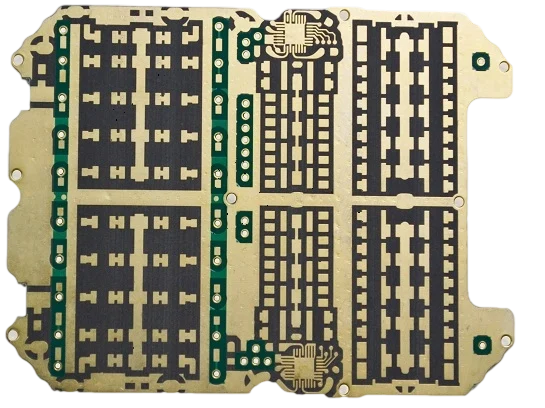
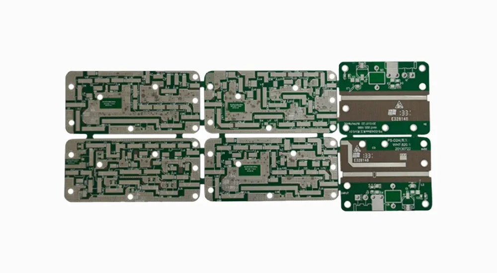
Rogers RO5880 is a PTFE-based composite laminate engineered specifically for high-frequency applications where signal integrity and low loss characteristics are paramount. The material combines the excellent electrical properties of PTFE with the mechanical stability required for modern PCB manufacturing processes.
Rogers RO5880 Electrical Properties
The electrical performance of Rogers RO5880 sets it apart from conventional PCB materials through several key parameters that directly impact circuit performance.
The dielectric constant (Dk) of Rogers RO5880 measures 2.20 ± 0.02 at 10 GHz, providing exceptional stability across frequency ranges. This low and consistent dielectric constant ensures predictable impedance control and minimal signal dispersion, making it ideal for applications requiring precise timing and signal integrity.
The dissipation factor (Df) of 0.0009 at 10 GHz represents one of the lowest loss tangents available in commercial PCB materials. This ultra-low loss characteristic translates directly to reduced signal attenuation and improved efficiency in high-frequency circuits.
| Property | Value | Impact on Performance |
|---|---|---|
| Dielectric Constant (Dk) | 2.20 ± 0.02 | Stable impedance control |
| Dissipation Factor (Df) | 0.0009 @ 10 GHz | Minimal signal loss |
| Volume Resistivity | 1.2 × 10¹⁰ Ω·cm | Excellent insulation |
| Surface Resistivity | 4.2 × 10⁹ Ω | Superior surface stability |
Thermal and Mechanical Properties
Rogers RO5880 demonstrates exceptional thermal stability with a coefficient of thermal expansion (CTE) of 31 ppm/°C in the X and Y directions. This low CTE ensures dimensional stability across temperature variations, reducing mechanical stress on components and solder joints.
The material maintains its electrical properties across a wide temperature range, with operating capabilities extending from -55°C to +200°C. This thermal resilience makes Rogers RO5880 suitable for aerospace, automotive, and industrial applications where temperature extremes are common.
Applications and Industry Use Cases
RF and Microwave Systems
Rogers RO5880 finds extensive application in RF and microwave circuits where signal integrity is non-negotiable. The material excels in power amplifier designs, where its low loss characteristics directly translate to improved efficiency and reduced heat generation. Antenna feed networks benefit from the stable dielectric properties, ensuring consistent radiation patterns and impedance matching across operational frequencies.
5G and Millimeter Wave Applications
The emergence of 5G technology and millimeter wave communications has created new demands for PCB materials capable of operating at frequencies exceeding 24 GHz. Rogers RO5880 meets these requirements through its consistent electrical properties at high frequencies, making it suitable for beamforming networks, phased array antennas, and high-speed digital interfaces.
Aerospace and Defense Electronics
Military and aerospace applications require materials that maintain performance under extreme conditions while providing long-term reliability. Rogers RO5880 addresses these needs through its thermal stability, low outgassing properties, and resistance to environmental factors such as humidity and chemical exposure.
Design Considerations for Rogers RO5880 PCBs
Impedance Control and Signal Integrity
Achieving precise impedance control with Rogers RO5880 requires careful attention to trace geometry and layer stackup design. The material’s stable dielectric constant allows for accurate impedance calculations and predictable performance across manufacturing tolerances.
Trace Width Calculations
For single-ended traces on Rogers RO5880, the relationship between trace width, substrate thickness, and target impedance follows standard transmission line equations. However, the low dielectric constant requires wider traces compared to conventional materials to achieve the same impedance values.
Differential Pair Design
Differential signaling applications benefit from Rogers RO5880’s consistent dielectric properties, which minimize skew between paired traces. The material’s low loss characteristics also reduce the need for signal conditioning or equalization in high-speed digital applications.
Thermal Management Strategies
While Rogers RO5880 offers good thermal conductivity for a PTFE-based material, effective thermal management remains important in high-power applications. Design strategies should include appropriate copper pour areas, thermal vias, and consideration of component placement to minimize hot spots.
Manufacturing Processes and Considerations
Fabrication Requirements
Manufacturing PCBs with Rogers RO5880 requires specialized processes and equipment due to the material’s unique properties. The PTFE-based composition demands careful handling during drilling, etching, and lamination to maintain material integrity and achieve desired performance characteristics.
1. Drilling and Via Formation
Mechanical drilling of Rogers RO5880 requires sharp, properly maintained drill bits and optimized feed rates to prevent material delamination or rough hole walls. Laser drilling offers advantages for small via formation, providing clean holes with minimal thermal damage to surrounding material.
2. Surface Preparation and Plating
The fluoropolymer surface of Rogers RO5880 requires special treatment for reliable copper adhesion. Sodium etching or plasma treatment creates the surface roughness necessary for strong metallization adhesion, ensuring long-term reliability of plated through holes and surface features.
Quality Control and Testing
Manufacturing Rogers RO5880 PCBs demands rigorous quality control processes to verify electrical performance and mechanical integrity. Critical parameters include dielectric constant uniformity, copper adhesion strength, and dimensional stability across temperature cycling.
1. Electrical Testing Protocols
High-frequency testing of Rogers RO5880 PCBs typically includes time domain reflectometry (TDR) measurements to verify impedance control, network analyzer measurements for insertion and return loss characterization, and dielectric constant verification through resonant cavity methods.
2. Environmental Testing
Environmental qualification testing ensures Rogers RO5880 PCBs maintain performance under operational conditions. Standard tests include thermal cycling, humidity exposure, and mechanical shock and vibration testing to verify long-term reliability.

Cost Optimization and Value Analysis
Initial Investment Considerations
Rogers RO5880 represents a premium material choice with correspondingly higher material costs compared to standard FR-4 substrates. However, the total cost of ownership often favors high-performance materials when considering the complete product lifecycle.
The superior electrical properties of Rogers RO5880 can eliminate the need for additional components such as equalizers or signal conditioning circuits, potentially offsetting higher material costs through simplified designs and improved yields.
Long-term Value Proposition
Applications requiring high reliability and consistent performance over extended periods benefit significantly from Rogers RO5880’s stable characteristics. The material’s resistance to environmental degradation and consistent electrical properties contribute to longer product lifecycles and reduced maintenance requirements.
Rogers RO5880 vs Alternative Materials
Comparison with Standard PTFE Materials
While Rogers RO5880 shares the excellent electrical properties of pure PTFE, its composite construction provides improved mechanical properties and manufacturability. The woven glass reinforcement offers better dimensional stability and easier handling during fabrication processes.
Performance Against Hydrocarbon-based Laminates
Hydrocarbon-based materials such as Rogers 4000 series offer cost advantages but cannot match the ultra-low loss characteristics of Rogers RO5880. For applications where maximum performance is required, particularly at millimeter wave frequencies, Rogers RO5880 provides superior signal integrity.
| Material Type | Dielectric Constant | Loss Tangent | Cost Relative to RO5880 |
|---|---|---|---|
| Rogers RO5880 | 2.20 | 0.0009 | Baseline |
| Rogers 4350B | 3.48 | 0.0037 | 60% |
| Standard PTFE | 2.10 | 0.0002 | 120% |
| FR-4 | 4.40 | 0.020 | 15% |
Future Developments and Industry Trends
The continued evolution of wireless communication standards and the push toward higher operating frequencies drive ongoing development in high-performance PCB materials. Rogers RO5880 continues to meet these evolving requirements through its proven performance characteristics and manufacturing compatibility.
Emerging applications in automotive radar, satellite communications, and Internet of Things (IoT) devices create new opportunities for Rogers RO5880 deployment. The material’s combination of electrical performance and manufacturing reliability positions it well for these growing markets.
Expert PCB Manufacturing with Haoyue Electronics
At Haoyue Electronics, we understand that selecting the right material is only the first step in creating high-performance PCBs. Our specialized manufacturing capabilities and extensive experience with Rogers RO5880 ensure that your high-frequency designs achieve their full potential.
Our advanced fabrication facilities are equipped with the specialized tooling and processes required for Rogers RO5880 manufacturing. From precision drilling and controlled impedance routing to specialized surface treatments and quality verification, we maintain the exacting standards necessary for mission-critical applications.
We invite you to partner with Haoyue Electronics for your next high-frequency PCB project. Our engineering team is ready to collaborate on design optimization, manufacturing process selection, and quality assurance protocols that ensure your Rogers RO5880 PCBs meet the most demanding performance requirements. Contact us today to discuss how our expertise can accelerate your product development timeline while maintaining the highest quality standards.
Frequently Asked Questions
1. What makes Rogers RO5880 suitable for 5G applications?
Rogers RO5880’s ultra-low loss tangent of 0.0009 and stable dielectric constant of 2.20 make it ideal for 5G millimeter wave frequencies. These properties ensure minimal signal attenuation and consistent performance across the wide frequency ranges used in 5G communications, from sub-6 GHz to mmWave bands above 24 GHz.
2. How does Rogers RO5880 compare to Rogers 4350B for cost-sensitive applications?
While Rogers 4350B offers significant cost savings at approximately 60% of RO5880’s material cost, it has a higher loss tangent (0.0037 vs 0.0009) and different dielectric constant (3.48 vs 2.20). Rogers RO5880 is justified when maximum performance is required, particularly above 10 GHz, while Rogers 4350B may be sufficient for lower frequency applications where cost is a primary concern.
3. What special manufacturing considerations apply to Rogers RO5880 PCBs?
Rogers RO5880 requires specialized surface treatment such as sodium etching or plasma treatment for reliable copper adhesion due to its PTFE base. Additionally, drilling parameters must be optimized to prevent delamination, and controlled impedance fabrication requires precise thickness control due to the material’s low dielectric constant.
4. Can Rogers RO5880 be used in multilayer PCB constructions?
Yes, Rogers RO5880 can be successfully incorporated into multilayer constructions, typically as core layers combined with appropriate prepreg materials. However, careful consideration of thermal expansion matching and lamination parameters is essential to maintain layer adhesion and prevent warpage during assembly processes.

