This Rogers PCB design guide explores the key material properties, application scenarios, and layout considerations that position RO4003C as a top-tier substrate for advanced circuits in telecommunications, aerospace, automotive radar, and industrial control electronics.
Material Properties of RO4003C
Rogers RO4003C demonstrates superior electrical and mechanical characteristics that distinguish it from conventional high-frequency PCB material options. The material’s hydrocarbon resin system combined with woven glass reinforcement creates a stable platform for high-frequency circuit designs.
Core Electrical Properties
The electrical performance of RO4003C centers on its carefully engineered dielectric characteristics that maintain consistency across varying operating conditions.
| Property | Specification | Test Condition |
|---|---|---|
| Dielectric Constant (Dk) | 3.38 ± 0.05 | 10 GHz |
| Dissipation Factor (Df) | 0.0027 | 10 GHz |
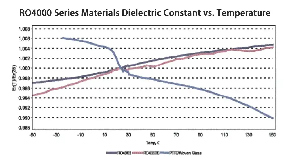
| Thermal Coefficient of Dk | -3 ppm/°C | -55°C to +125°C |
| Volume Resistivity | >10⁶ MΩ·cm | 23°C / 50% RH |
| Surface Resistivity | >10⁶ MΩ | 23°C / 50% RH |
Thermal and Mechanical Stability
The mechanical stability of RO4003C ensures reliable performance under thermal cycling and mechanical stress conditions typical in modern electronic assemblies.
| Property | Value | Standard |
|---|---|---|
| Z-Axis Thermal Expansion | 24 ppm/°C | 50-260°C |
| Glass Transition Temperature (Tg) | >280°C | DSC |
| Thermal Decomposition (T288) | >60 minutes | TGA |
| Moisture Absorption | <0.05% | 24 hrs / 23°C |
| Peel Strength | >8 lbs/in | IPC-TM-650 |
Key Features and Performance Characteristics
Low-Loss Signal Transmission
The exceptional dissipation factor of 0.0027 at 10 GHz enables this low-loss PCB substrate to maintain signal integrity across extended frequency ranges. This low-loss characteristic translates directly to improved system performance through reduced signal attenuation and enhanced power efficiency in RF applications.
Dimensional Stability
RO4003C exhibits minimal dimensional change across temperature variations, ensuring consistent impedance control and reliable mechanical registration during assembly processes. The controlled thermal expansion coefficient prevents warpage and maintains precise trace geometries critical for high-frequency circuits.
Processing Compatibility
The material demonstrates compatibility with standard PCB fabrication processes while operating at lower processing speeds compared to conventional FR-4 materials. This characteristic allows manufacturers to utilize existing equipment and processes with minor adjustments to accommodate the material’s specific requirements.

Applications of RO4003C Laminate
RF and Microwave Systems
RO4003C serves as the foundation for numerous RF and microwave applications where precise impedance control and minimal signal loss determine system performance. The material excels in applications operating from several hundred megahertz to tens of gigahertz.
Key applications include:
- Power amplifiers and low-noise amplifiers
- Antenna feed networks and RF filters
- Microwave communication systems
- Radar and satellite communication equipment
Automotive Radar Technology
Modern automotive safety systems rely heavily on radar technology for collision avoidance, adaptive cruise control, and autonomous driving features. RO4003C provides the stable platform required for 24 GHz and 77 GHz automotive radar systems, where signal accuracy directly impacts safety performance.
Cellular Infrastructure
Base station antennas and power amplifiers utilize RO4003C for its ability to handle high power levels while maintaining low insertion loss. The material’s thermal stability ensures reliable operation under the demanding conditions typical in cellular infrastructure equipment.
High-Speed Digital Applications
RO4003C is primarily known for RF and microwave applications. However, it also supports high-speed digital circuits where controlled impedance and low skew requirements exceed the capabilities of standard materials. Applications include high-speed backplanes, memory interfaces, and data communication systems.
Advantages and Design Considerations
Primary Advantages
RO4003C offers several compelling advantages that position it as a preferred material for demanding applications. The low dielectric constant enables compact circuit designs while maintaining controlled impedance characteristics. The material’s wide frequency capability supports both narrowband and broadband applications within a single substrate.
Cost effectiveness represents another significant advantage, particularly when compared to specialized PTFE-based materials. The processing similarity to FR-4 reduces manufacturing complexity while delivering performance characteristics approaching more expensive alternatives.
Design Limitations
Engineers must consider several limitations when specifying RO4003C for specific applications. The material lacks inherent flame retardancy, requiring additional measures to meet fire safety requirements in certain applications. This characteristic limits its use in applications where UL 94 compliance is mandatory without additional flame-retardant treatments.
The material’s processing requirements differ from standard FR-4, necessitating adjusted drilling parameters and via processing techniques. These modifications may impact manufacturing throughput and require process optimization for high-volume production.
Stackup Design Optimization for High-Frequency Performance
Understanding how RO4003C laminate performs within different microwave PCB stackup configurations enables engineers to optimize signal integrity and electromagnetic performance. The material’s consistent dielectric properties provide predictable behavior across various transmission line structures commonly employed in high-frequency designs.
Microstrip Configuration Performance
In microstrip implementations, RO4003C demonstrates excellent impedance control consistency due to its stable dielectric constant. The material’s low-loss characteristics minimize signal attenuation even in longer trace lengths, making it particularly suitable for power amplifier and antenna feed applications. The hydrocarbon resin system provides superior thermal stability compared to traditional materials, ensuring reliable impedance maintenance across temperature variations.
Ground-Signal-Ground Stackup Benefits
Ground-Signal-Ground configurations utilizing RO4003C as the core dielectric material achieve superior isolation between signal layers. This high-frequency PCB material effectively suppresses crosstalk and electromagnetic interference while maintaining controlled impedance characteristics. The material’s low moisture absorption ensures stable electrical performance in multilayer implementations where environmental conditions may vary.
Coplanar Waveguide Implementation
Coplanar waveguide structures benefit significantly from RO4003C’s uniform dielectric properties and low-loss characteristics. The material enables precise field control and impedance matching in applications requiring minimal radiation and maximum isolation. This configuration proves particularly valuable in millimeter-wave applications where traditional stripline approaches may introduce excessive loss.
Manufacturing and Processing Guidelines
Drilling and Via Formation
RO4003C requires specific drilling parameters to achieve optimal via quality and reliability. Reduced drilling speeds and modified entry/exit materials help prevent delamination and ensure clean via formation. Due to its woven glass structure, optimal drill bit life and precision require controlled parameters and regular tool inspection.
Copper Adhesion and Plating
The hydrocarbon resin system necessitates appropriate surface preparation techniques to ensure reliable copper adhesion. Plasma treatment or chemical etching may be required to achieve the surface energy necessary for consistent plating adhesion and long-term reliability.
Thermal Management During Assembly
The material’s thermal characteristics require careful attention during assembly processes. Reflow profiles must account for the material’s thermal expansion properties and glass transition temperature to prevent warpage and maintain joint integrity.
Material Selection Criteria
Frequency Range Considerations
RO4003C demonstrates optimal performance characteristics across the frequency spectrum from several hundred megahertz to approximately 40 GHz. Applications requiring operation beyond this range may benefit from specialized materials with enhanced high-frequency performance.
Environmental Requirements
The low moisture absorption characteristics of RO4003C make it suitable for applications exposed to humid environments. However, applications requiring operation in extreme chemical environments may require additional protective measures or alternative material selection.
Cost-Performance Balance
The material provides an optimal balance between performance and cost for many high-frequency applications. The processing compatibility with existing equipment reduces implementation costs while delivering performance characteristics previously available only in more expensive specialty materials.
Design Techniques with RO4003C
Microstrip and Stripline Configurations
RO4003C supports various transmission line configurations essential for high-frequency circuit design. Microstrip configurations benefit from the material’s stable dielectric properties, enabling precise impedance control across wide frequency ranges. Stripline implementations utilize the material’s consistent thickness and low-loss characteristics for optimal signal isolation and controlled impedance.
Controlled Impedance Requirements
The material’s stable dielectric constant enables reliable controlled impedance design across temperature variations. This stability proves critical for high-speed digital applications where impedance mismatches can cause signal reflections and timing errors. The predictable electrical characteristics allow designers to achieve target impedances with minimal iteration.
Differential Pair Implementation
High-speed differential signaling applications benefit from RO4003C’s consistent dielectric properties and low skew characteristics. The material enables tight coupling between differential pairs while maintaining controlled impedance and minimizing crosstalk between adjacent signal pairs.
RO4003C vs Other PCB Materials
RO4003C vs FR-4
While FR-4 remains the standard for general-purpose applications, RO4003C provides significant advantages for high-frequency designs. The lower dielectric constant and reduced loss tangent of RO4003C enable improved signal integrity and reduced power consumption in RF applications. However, FR-4 maintains cost advantages for applications not requiring high-frequency performance.
RO4003C vs PTFE-Based Materials
PTFE-based materials offer superior electrical performance at higher frequencies but require specialized processing techniques and higher material costs. This RO4003C laminate provides a cost-effective alternative for applications operating below 40 GHz while maintaining compatibility with standard PCB fabrication processes.
Future Developments and Industry Trends
The continuous evolution of electronic systems toward higher frequencies and increased integration drives ongoing development in PCB materials technology. RO4003C represents a mature technology platform that continues to meet the requirements of emerging applications while serving as a benchmark for new material developments.
Emerging applications in 5G communications, automotive electronics, and aerospace systems continue to expand the demand for reliable, cost-effective high-frequency materials. The proven performance record of RO4003C positions it well to serve these growing market segments.
Professional PCB Manufacturing with RO4003C
At Haoyue Electronics, we specialize in manufacturing and assembling high-performance PCBs using Rogers RO4003C and other advanced materials. Our engineering team possesses extensive experience in optimizing designs for high-frequency applications, ensuring your projects achieve optimal performance while meeting cost and schedule requirements.
Our state-of-the-art manufacturing facility maintains the precise process controls necessary for working with specialty materials like RO4003C. From prototype development through high-volume production, we provide comprehensive support for your most demanding electronic projects. Contact our engineering team to discuss how Rogers RO4003C can enhance your next high-frequency design.
FAQ
1. Can RO4003C be processed using standard PCB manufacturing equipment?
RO4003C demonstrates excellent compatibility with conventional PCB fabrication equipment, though certain process parameters require adjustment. The material processes similarly to FR-4 but operates at reduced speeds to ensure optimal quality. Standard drilling, plating, and etching equipment can accommodate RO4003C with appropriate parameter modifications.
The primary adjustments involve slower drilling speeds, modified entry and exit materials for via formation, and careful attention to thermal profiles during assembly processes. This compatibility advantage significantly reduces implementation costs compared to specialized PTFE-based materials that require dedicated processing equipment.
2. When should engineers choose RO4003C over FR-4 or other high-frequency materials?
Engineers should select RO4003C when applications require superior electrical performance beyond FR-4 capabilities while maintaining cost effectiveness. The material proves optimal for designs operating above 1 GHz where signal integrity, controlled impedance, and low loss become critical factors.
RO4003C offers significant advantages over FR-4 in RF applications, power amplifiers, and high-speed digital circuits where insertion loss and impedance stability directly impact system performance. Compared to PTFE-based alternatives, RO4003C provides adequate performance for frequencies below 40 GHz at substantially lower material and processing costs. The decision should consider frequency requirements, performance specifications, volume production needs, and budget constraints.
3. What are the primary design challenges when working with RO4003C laminates?
The most significant design challenge involves the material’s lack of inherent flame retardancy, which requires additional considerations for applications with strict fire safety requirements. Engineers must implement appropriate flame-retardant measures or select alternative materials for applications requiring UL 94 compliance.
Another consideration involves the material’s processing requirements, which differ from standard FR-4 and may impact manufacturing throughput in high-volume applications. The hydrocarbon resin system also requires specific surface preparation techniques to ensure reliable copper adhesion. Additionally, while RO4003C excels in RF applications, it may not provide optimal performance for extremely high-speed digital applications requiring the absolute lowest loss characteristics available in more specialized materials.
4. How does temperature variation affect RO4003C performance in real-world applications?
RO4003C demonstrates excellent thermal stability with a thermal coefficient of dielectric constant of -3 ppm/°C, ensuring consistent electrical performance across operating temperature ranges. This stability proves particularly valuable in automotive and aerospace applications where temperature variations can span extreme ranges. The material maintains controlled impedance characteristics and signal integrity even under thermal cycling conditions typical in modern electronic systems.
However, engineers should account for the material’s thermal expansion properties during design and assembly processes. The Z-axis thermal expansion of 24 ppm/°C requires consideration in multilayer stackups and via design to prevent reliability issues. Proper thermal management during assembly ensures optimal long-term performance and prevents warpage or dimensional instability that could affect electrical characteristics.

