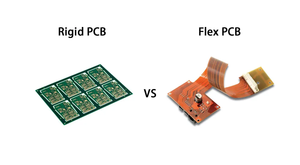
Engineers evaluating rigid and flex PCB options must account for various factors such as mechanical properties, electrical performance, PCB manufacturing processes, and specific application requirements. This comprehensive comparison explores the fundamental differences between rigid and flexible PCBs, offering valuable technical insights to help optimize your electronic product design decisions.
Understanding the unique advantages and limitations of both rigid and flexible printed circuit boards is essential for engineers aiming to deliver efficient, reliable, and cost-effective electronic solutions.
Comprehensive Rigid PCB vs Flex PCB Comparison
| Comparison Factor | Rigid PCB | Flex PCB |
|---|---|---|
| Substrate Material | FR-4 fiberglass-epoxy composite | Polyimide or polyester film |
| Copper Type | Electrodeposited copper | Rolled annealed copper |
| Flexibility | No flexibility, rigid structure | High flexibility, bendable design |
| Thickness Range | 0.4mm - 6.0mm (standard 1.6mm) | 0.1mm - 0.5mm (typical 0.2mm) |
| Layer Count | 1-30+ layers possible | 1-8 layers typical |
| Dielectric Constant | 4.3 (FR-4 at 1MHz) | 3.5 (Polyimide at 1MHz) |
| Operating Temperature | -40°C to +130°C | -200°C to +200°C |
| Bend Radius | Not applicable | 6× thickness (static), 10× (dynamic) |
| Component Density | Very high density possible | Limited by flexibility requirements |
| Via Technology | Through-hole, blind, buried, microvias | Through-hole, limited blind vias |
| Surface Protection | Solder mask | Coverlay (polyimide + adhesive) |
| Minimum Trace Width | 75μm (inner), 100μm (outer) | 100μm standard, 75μm achievable |
| Manufacturing Complexity | Standard, well-established | Specialized processes required |
| Lead Time | 1–3 weeks standard | 2–4 weeks standard |
| Design Software | All major CAD tools | Specialized flex design tools |
| Testing Methods | Standard electrical testing | Electrical + flex life testing |
| Assembly Method | Standard SMT/THT processes | Modified assembly techniques |
| Connector Requirements | Multiple connectors typical | Eliminates many connectors |
| Weight | Heavier due to substrate | 75% lighter than equivalent rigid |
| Vibration Resistance | Good with proper mounting | Excellent, absorbs vibration |
| EMI Shielding | Excellent with ground planes | Good with hatched ground planes |
| Repair Capability | Standard repair techniques | Limited repair options |
| Volume Production | Highly scalable | Moderate scalability |
| Initial Cost | Lower material and process cost | 2–5× higher than rigid equivalent |
| System Cost Impact | Additional connectors/cables | Reduces assembly components |
| Typical Applications | Computers, appliances, automotive ECUs | Medical devices, aerospace, wearables |
| Market Availability | Worldwide, numerous suppliers | Specialized suppliers, limited |
| Standards Compliance | IPC-2221, IPC-6012 | IPC-2223, IPC-6013 |
Understanding Rigid PCB and Flex PCB Construction
Rigid PCB Construction and Materials
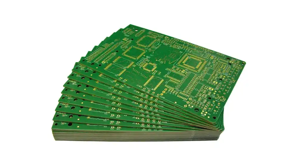
Rigid printed circuit boards utilize a fiberglass-reinforced epoxy resin substrate, typically FR-4, which provides exceptional mechanical stability and dimensional accuracy. The substrate construction consists of woven glass fabric impregnated with flame-retardant epoxy resin, creating a composite material with excellent electrical insulation properties and superior thermal performance.
The copper conductor layers in rigid PCBs are formed through electrodeposition processes, resulting in uniform thickness and excellent conductivity. Multiple copper layers can be laminated together with prepreg materials to create multilayer rigid PCB designs supporting complex electronic circuits. The surface finish options include HASL (Hot Air Solder Leveling), ENIG (Electroless Nickel Immersion Gold), and OSP (Organic Solderability Preservative), each offering specific advantages for component assembly processes.
Rigid PCB stackup configurations can accommodate high-density interconnect (HDI) designs with microvias, buried vias, and blind vias, enabling compact electronic layouts while maintaining signal integrity. The standardized thickness options range from 0.4mm to 6.0mm, with typical four-layer boards measuring 1.6mm in thickness.
Flex PCB Construction and Materials
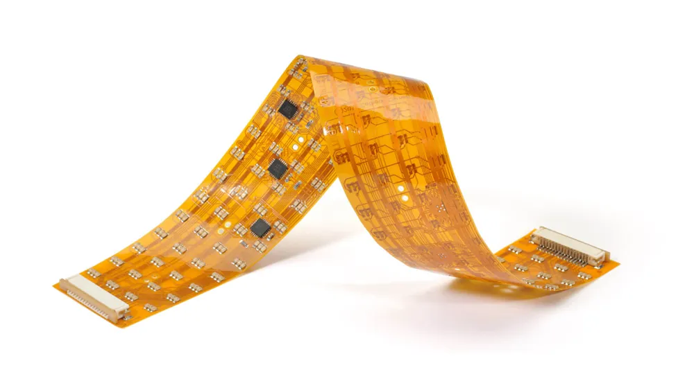
Flexible printed circuits employ polyimide or polyester film substrates that maintain electrical properties while providing mechanical flexibility. Polyimide substrates offer superior temperature resistance (up to 260°C), chemical stability, and dimensional stability compared to polyester alternatives, making them the preferred choice for demanding applications.
The conductive layers in flex PCBs utilize rolled annealed copper, which exhibits enhanced flexibility compared to electrodeposited copper used in rigid boards. The annealing process reduces copper grain structure, allowing the material to withstand repeated flexing without fatigue failure. Conductor thickness typically ranges from 12 to 70 micrometers, with 35-micrometer copper being most common for general applications.
Flexible PCB protection utilizes coverlay materials instead of traditional solder mask, providing environmental protection while maintaining flexibility. The coverlay consists of polyimide film with acrylic adhesive, creating a barrier against moisture, chemicals, and mechanical damage. Stiffener materials can be selectively applied to specific areas requiring enhanced rigidity for component mounting or connector attachment.
Performance Characteristics Comparison
Electrical Performance
The electrical characteristics of rigid PCB vs flex PCB designs exhibit distinct differences that influence signal integrity and electromagnetic compatibility. Rigid PCBs provide consistent dielectric properties across the entire board area, with FR-4 substrate offering a dielectric constant of approximately 4.3 at 1MHz. This stability enables predictable impedance control and minimal signal distortion in high-frequency applications.
Flexible printed circuits present more complex electrical considerations due to their dynamic nature. The polyimide substrate exhibits a lower dielectric constant (approximately 3.5) compared to FR-4, potentially offering improved high-frequency performance. However, the electrical properties can vary during flexing operations, requiring careful design considerations for critical signal paths.
| Performance Parameter | Rigid PCB | Flex PCB |
|---|---|---|
| Dielectric Constant | 4.3 (FR-4) | 3.5 (Polyimide) |
| Maximum Operating Temperature | 130°C (FR-4) | 200°C (Polyimide) |
| Conductor Thickness Range | 17.5–105 μm | 12–70 μm |
| Via Technology | Through-hole, Blind, Buried | Through-hole, Limited blind |
| Minimum Trace Width | 75 μm (standard) | 100 μm (standard) |
Mechanical Properties
The mechanical characteristics represent the most significant differentiator in rigid PCB vs flex PCB comparison. Rigid boards provide exceptional mechanical support for heavy components, with flexural strength exceeding 400 MPa and excellent dimensional stability under thermal cycling. The glass transition temperature (Tg) of FR-4 substrates typically ranges from 130°C to 180°C, ensuring structural integrity across normal operating temperatures.
Flexible circuits offer unique mechanical advantages including resistance to vibration, shock absorption, and the ability to eliminate mechanical connectors through three-dimensional routing. The flex life of quality polyimide-based circuits can exceed one million bend cycles when properly designed, with bend radius capabilities down to six times the circuit thickness for dynamic applications.
Environmental Resistance
Environmental performance considerations significantly impact the long-term reliability of electronic assemblies. Rigid PCBs demonstrate excellent resistance to moisture absorption, with typical values below 0.1% by weight under standard test conditions. The flame-retardant properties of FR-4 substrates provide UL 94 V-0 rating, ensuring fire safety compliance in most applications.
Flexible printed circuits exhibit superior chemical resistance due to the inherent properties of polyimide substrates. The low moisture absorption (less than 0.3%) and excellent thermal stability make flex circuits suitable for harsh environmental conditions. However, the exposed conductor edges in flex circuits require careful environmental sealing to prevent corrosion in humid or contaminated environments.

Design Considerations and Manufacturing
Design Guidelines for Rigid PCBs
Rigid PCB design optimization focuses on maximizing component density while maintaining manufacturability and signal integrity. Standard design rules include minimum trace width of 100 micrometers for outer layers and 75 micrometers for inner layers, with via sizes typically ranging from 200 to 600 micrometers depending on board thickness and layer count.
Thermal management becomes critical in rigid PCB designs supporting high-power components. Copper pour areas, thermal vias, and strategic component placement help distribute heat effectively across the board surface. Ground plane design and power distribution networks require careful consideration to minimize electromagnetic interference and ensure stable power delivery to all components.
Flex PCB Design Requirements
Flexible circuit design demands specialized considerations to ensure mechanical reliability and electrical performance. Bend radius calculations must account for conductor stress, with static bend radius typically requiring minimum six times the circuit thickness and dynamic applications requiring ten times the thickness to prevent fatigue failure.
Conductor routing in flex circuits requires curved traces rather than sharp angles to minimize stress concentration during flexing. Hatched ground planes replace solid copper pours in flex areas to maintain flexibility while providing electromagnetic shielding. Component placement must consider mechanical stress distribution, with critical components positioned in rigid areas or supported by local stiffeners.
Manufacturing Process Differences
The manufacturing processes for rigid PCB vs flex PCB production involve distinct techniques and equipment requirements. Rigid PCB fabrication follows standardized processes including drilling, plating, etching, and lamination using conventional panel processing methods. The well-established manufacturing infrastructure enables cost-effective production with short lead times for standard configurations.
Flexible circuit manufacturing requires specialized handling and processing techniques to maintain substrate integrity throughout production. Roll-to-roll processing capabilities enable efficient production of simple flex circuits, while panel processing accommodates complex multilayer designs. The coverlay application process replaces traditional solder mask application, requiring precise registration and controlled adhesive flow.

Applications and Cost Analysis
Optimal Applications for Each Type
Rigid PCB technology remains the optimal choice for applications requiring maximum component density, robust mechanical support, and cost-effective manufacturing. Consumer electronics including smartphones, tablets, and computers utilize rigid boards for main processing circuits where space constraints and component complexity drive design decisions. Industrial control systems, automotive engine management, and telecommunications infrastructure benefit from the proven reliability and thermal performance of rigid PCB designs.
Flexible printed circuits excel in applications requiring three-dimensional routing, space optimization, and dynamic mechanical performance. Medical devices utilize flex circuits for patient monitoring equipment and implantable devices where biocompatibility and flexibility are essential. Aerospace applications leverage the weight reduction and vibration resistance of flex circuits in satellite systems and aircraft instrumentation. Wearable technology depends on flexible circuits to accommodate body movement while maintaining electrical connectivity.
Cost Considerations and ROI
The initial cost comparison between rigid PCB vs flex PCB typically favors rigid boards due to mature manufacturing processes and material costs. Standard rigid PCBs cost approximately 30–50% less than equivalent flex circuits for simple designs. However, comprehensive cost analysis must consider system-level implications including connector elimination, assembly labor reduction, and improved reliability.
Flexible circuits often provide overall cost advantages in complex assemblies by eliminating multiple rigid boards and interconnecting cables. The three-dimensional routing capability reduces system volume, potentially enabling smaller enclosures and reduced material costs. Reliability improvements through connector elimination can significantly reduce field service costs and warranty claims in critical applications.
Long-term return on investment calculations should include manufacturing yield improvements, reduced assembly time, and enhanced product differentiation capabilities that flex circuits enable. Applications requiring frequent product updates or customization benefit from the design flexibility that flex circuits provide compared to rigid board alternatives.
Ready to optimize your next electronic design project?
Haoyue Electronics brings over a decade of expertise in both rigid PCB manufacturing and flexible circuit production. Our engineering team collaborates with clients to determine the optimal PCB technology for each application, ensuring superior performance while managing project costs effectively.
From prototype development through high-volume production, we deliver precision-manufactured printed circuit boards that meet the most demanding technical requirements. Contact our technical specialists today to discuss how our comprehensive PCB manufacturing capabilities can accelerate your product development timeline and enhance your competitive advantage in the marketplace.

