Introduction
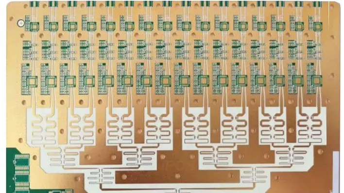
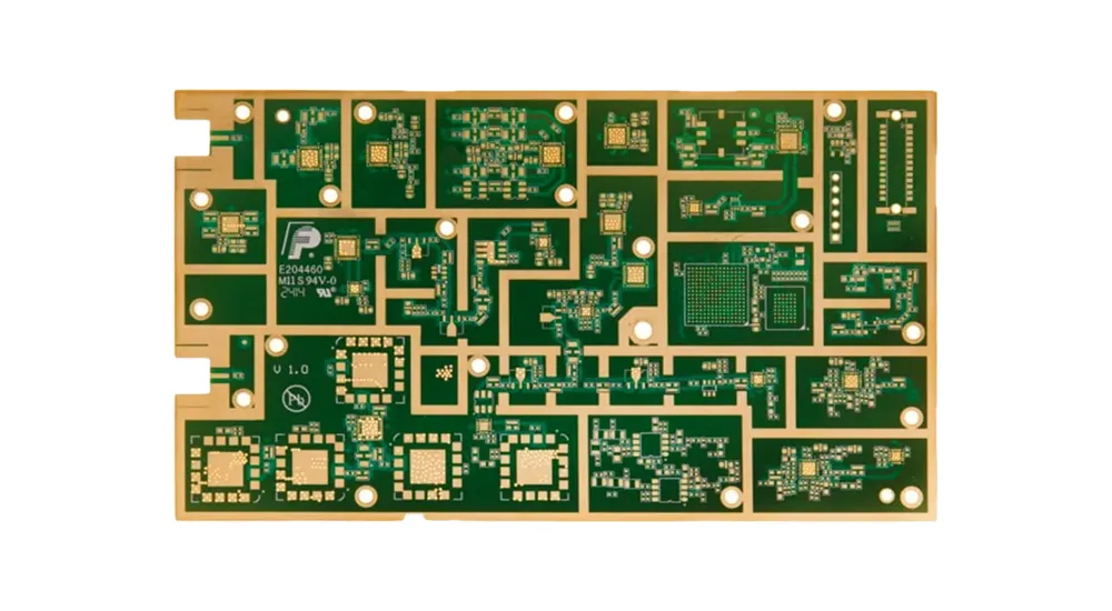
RF and Microwave PCBs represent a specialized category of printed circuit boards engineered to handle high-frequency signals with minimal loss and precise impedance control. These sophisticated substrates form the backbone of modern wireless communication systems, from 5G infrastructure to advanced radar applications, where standard FR4 materials simply cannot deliver the required performance parameters.
Unlike conventional PCBs designed for digital applications, RF and Microwave PCBs must maintain signal integrity across frequency ranges spanning from hundreds of megahertz to tens of gigahertz. This fundamental requirement drives every aspect of their design, material selection, and manufacturing processes.
Defining RF and Microwave PCB Technology
RF and Microwave PCBs are purpose-built printed circuit boards optimized for radio frequency and microwave signal transmission. The distinction lies primarily in their operating frequency ranges and the corresponding technical requirements.
RF PCBs typically operate within the 100 MHz to 1 GHz spectrum, encompassing applications such as cellular communications, FM radio, and lower-frequency wireless systems. Microwave PCBs extend this capability into the 1 GHz to 30+ GHz range, supporting applications including millimeter-wave radar, satellite communications, and advanced 5G systems.
The core differentiator between these specialized PCBs and standard boards lies in their ability to maintain consistent dielectric properties, minimize transmission losses, and provide precise impedance control across their designated frequency ranges.
Frequency Range Classifications and Technical Implications
RF PCB Frequency Characteristics (100 MHz – 1 GHz)
At these frequencies, material selection begins to significantly impact signal behavior. Standard FR4 materials exhibit increasing dielectric losses and frequency-dependent variations in dielectric constant, making them unsuitable for precision RF applications.
Microwave PCB Frequency Characteristics (1 GHz – 30+ GHz)
Microwave frequencies demand materials with ultra-stable dielectric constants and minimal loss tangents. At these frequencies, even minor variations in substrate thickness or copper surface roughness can significantly impact signal integrity.
Millimeter-Wave Considerations (30+ GHz)
Emerging applications in automotive radar (77 GHz) and future 6G communications push requirements even further, demanding specialized ceramic substrates and advanced manufacturing techniques.

RF & Microwave PCB
Critical Applications of RF and Microwave PCBs
5G Infrastructure Systems utilize these specialized PCBs in base station RF front-ends, massive MIMO antenna arrays, and beamforming networks where precise phase relationships must be maintained across multiple signal paths.
Radar Systems represent perhaps the most demanding application, particularly in automotive millimeter-wave radar operating at 77 GHz, where PCB performance directly affects detection range and resolution capabilities.
Satellite and Aerospace Communications require RF and Microwave PCBs capable of operating reliably in extreme environments while maintaining stable electrical performance across wide temperature ranges.
Consumer Electronics increasingly incorporate these specialized boards in high-performance Wi-Fi 6E routers, 5G smartphones, and IoT devices requiring robust wireless connectivity.
Fundamental Differences: RF/Microwave vs Standard PCB Technology
Material Science and Substrate Selection
Standard PCBs rely on FR4 fiberglass composite with a dielectric constant (Dk) of approximately 4.5 and loss tangent (Df) around 0.02. While adequate for digital applications, FR4 exhibits significant frequency-dependent variations that render it unsuitable for high-frequency applications.
RF and Microwave PCBs utilize advanced materials including Rogers RO4000 and RO6000 series laminates, Taconic ceramic-filled PTFE substrates, and Arlon thermoset microwave materials. These materials maintain stable dielectric constants (typically 2.2 to 10.2) and ultra-low loss tangents (0.0009 to 0.004) across their operating frequency ranges.
Design Architecture and Signal Management
RF and Microwave PCB design requires sophisticated transmission line structures including microstrip, stripline, and coplanar waveguide configurations. Each topology offers specific advantages for impedance control and signal containment.
Ground plane design becomes critical at high frequencies, with techniques such as via stitching and guard traces essential for maintaining signal integrity and preventing unwanted coupling between adjacent circuits.
Manufacturing Precision Requirements
High-frequency PCB manufacturing demands tolerances significantly tighter than standard boards. Dielectric thickness variations must be controlled to ±0.0005 inches or better, while copper surface roughness directly impacts insertion loss at microwave frequencies.
Advanced Material Technologies for High-Frequency Applications
Rogers Corporation Materials
Rogers RO4000 series materials offer excellent electrical performance with low dielectric loss and stable dielectric constant across frequency and temperature. The RO4350B variant provides a dielectric constant of 3.48 ± 0.05 and loss tangent of 0.0037 at 10 GHz.
Rogers RO6000 series extends performance into millimeter-wave applications with ultra-low loss characteristics and excellent dimensional stability.
Taconic Advanced Dielectric Division Materials
Taconic offers ceramic-filled PTFE substrates such as TLY-5 and CER-10, providing superior thermal stability and low moisture absorption characteristics essential for aerospace applications.
Arlon Materials and Technologies
Arlon 25N and AD series materials combine low loss performance with excellent thermal conductivity, making them suitable for high-power RF applications where heat dissipation is critical.
Ceramic Substrates
Aluminum oxide and aluminum nitride ceramic substrates provide exceptional thermal management capabilities for high-power microwave applications, though they require specialized manufacturing processes.
Design Guidelines and Engineering Considerations
Successful RF and Microwave PCB design requires adherence to established transmission line principles. Microstrip line impedance depends on trace width, substrate thickness, and dielectric constant according to well-established formulas that must be verified through electromagnetic simulation.
Layer stackup design becomes increasingly complex at high frequencies, with careful attention to signal layer spacing, ground plane integrity, and via design. Each via represents a potential discontinuity that can degrade signal performance through reflection and radiation.
Electromagnetic compatibility considerations require careful attention to trace routing, component placement, and shielding techniques to prevent interference between circuits and ensure regulatory compliance.
Manufacturing Excellence for RF and Microwave PCBs
Manufacturing high-frequency PCBs requires specialized equipment and processes not typically found in standard PCB fabrication facilities. Controlled impedance testing must be performed at actual operating frequencies rather than relying on low-frequency approximations.
Surface finishes such as Electroless Nickel Immersion Gold (ENIG) provide excellent soldering characteristics while maintaining low RF losses. Alternative finishes including Immersion Silver and Organic Solderability Preservative (OSP) may be selected based on specific application requirements.
Drill quality becomes critical at microwave frequencies, with via barrel roughness directly impacting insertion loss. Advanced drilling techniques and surface treatment processes are essential for maintaining optimal electrical performance.
Future Technology Trends and Market Drivers
The evolution toward 6G communications systems will drive demand for PCBs capable of operating reliably at frequencies approaching 100 GHz. This progression requires continued advancement in material science and manufacturing precision.
Autonomous vehicle development accelerates demand for sophisticated radar systems operating at 77 GHz and potentially higher frequencies, requiring PCB technologies capable of supporting these demanding applications.
The Internet of Things expansion creates opportunities for high-volume, cost-effective RF PCB solutions that maintain performance while achieving manufacturing economies suitable for consumer applications.
Why Choose Haoyue Electronics for Your RF and Microwave PCB Projects
Haoyue Electronics combines advanced manufacturing capabilities with deep technical expertise to deliver reliable RF and Microwave PCB solutions for demanding applications. Our comprehensive capabilities include:
- Advanced Material Handling: Complete processing capabilities for Rogers, Taconic, Arlon, and ceramic substrates with certified material handling procedures
- Precision Manufacturing: Controlled impedance capabilities to ±5% tolerance with high-frequency testing verification up to 20 GHz
- Complete Assembly Services: Full turnkey RF PCB assembly including precision component placement and specialized soldering techniques for high-frequency components
- Quality Assurance: Comprehensive testing protocols including network analyzer validation and thermal cycling qualification
- Engineering Support: Technical consultation services for stackup optimization, impedance matching, and electromagnetic compatibility
Our manufacturing facility maintains ISO 9001 certification with specialized processes for high-frequency applications. We understand that RF and Microwave PCB projects require both technical precision and reliable delivery schedules.
Frequently Asked Questions
What distinguishes RF PCBs from Microwave PCBs?
The primary distinction lies in operating frequency ranges: RF PCBs typically operate from 100 MHz to 1 GHz, while Microwave PCBs extend from 1 GHz to 30+ GHz, with correspondingly different material and design requirements.
Why are Rogers materials preferred for RF and Microwave applications?
Rogers materials offer stable dielectric constants and low loss tangents across frequency and temperature ranges, providing consistent electrical performance essential for high-frequency applications.
How do manufacturing tolerances differ for high-frequency PCBs?
RF and Microwave PCBs require significantly tighter tolerances than standard boards, particularly for dielectric thickness (±0.0005 inches) and trace geometry to maintain impedance control.
What applications drive the highest performance requirements?
Millimeter-wave radar systems, satellite communications, and 5G infrastructure represent the most demanding applications, requiring materials and manufacturing processes at the current limits of PCB technology.
How does substrate selection impact overall system performance?
Substrate dielectric constant and loss tangent directly affect signal speed, attenuation, and impedance characteristics, making material selection critical for meeting system performance specifications.

