Introduction
The choice between standard PCB and high speed PCB designs represents a critical decision point for electronics engineers and procurement professionals. As electronic systems evolve toward higher data rates and more complex signal processing requirements, understanding when to implement high speed PCB design becomes essential for project success. This comprehensive comparison examines the fundamental differences, design requirements, and manufacturing considerations that distinguish these two PCB categories.

What is a Standard PCB?
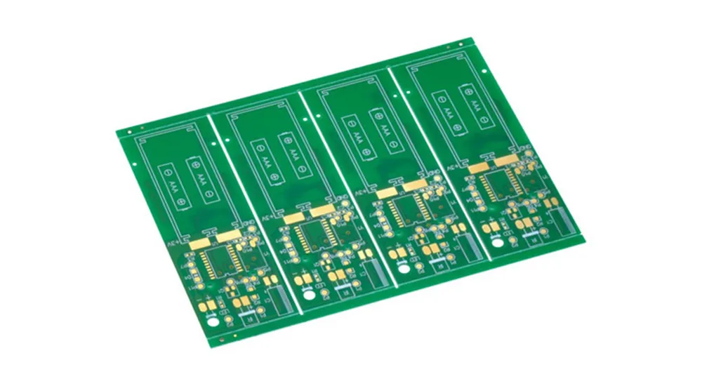
A standard PCB serves as the foundation for conventional electronic products operating at lower frequencies and data rates. These boards typically handle signals below 1 GHz and feature relatively slow edge rates that minimize signal integrity concerns. Standard PCB design prioritizes cost-effectiveness and manufacturing simplicity, making them ideal for consumer electronics, basic industrial controls, and traditional communication systems.
Key characteristics of standard PCBs include straightforward design rules, minimal impedance control requirements, and widespread use of FR4 substrate materials. The manufacturing process follows established industry practices with standard via structures and conventional layer stackups that keep production costs low while maintaining reliable performance for most applications.

What is a High Speed PCB?
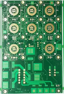
High speed PCB design addresses the complex requirements of modern electronic systems where signal frequencies exceed 1 GHz or edge rates fall below 1 nanosecond. The question “what is high speed PCB” encompasses boards that demand precise signal integrity management, controlled impedance routing, and specialized materials to maintain signal quality across the circuit.
These boards serve critical applications in 5G telecommunications, artificial intelligence servers, data center infrastructure, and advanced automotive electronics. High speed PCB design requires extensive knowledge of electromagnetic theory, material properties, and manufacturing precision to achieve optimal performance in demanding environments.
Key Differences Between Standard PCB and High Speed PCB
| Design Aspect | Standard PCB | High Speed PCB |
|---|---|---|
| Signal Frequency | Typically < 1 GHz | > 1 GHz or fast edge rates |
| Design Rules | Basic routing guidelines | Controlled impedance, differential pairs, length matching |
| Materials | FR4 substrate | Rogers, Megtron, low-loss dielectrics |
| Via Structure | Through-hole vias | HDI, blind/buried vias, microvias |
| Layer Count | 2-8 layers typical | 6-20+ layers common |
| Trace Width/Spacing | Standard manufacturing rules | Fine-pitch requirements |
| Testing Requirements | Basic electrical testing | Signal integrity, impedance, TDR testing |
| Cost | Low to moderate | Moderate to high |
| Lead Time | Standard production | Extended due to specialized processes |
Signal Integrity Design Challenges in High Speed PCBs
Signal integrity represents the most critical aspect distinguishing high speed PCB design from standard approaches. When signals transition rapidly or operate at high frequencies, several electromagnetic phenomena emerge that can severely impact circuit performance if not properly managed.
Transmission Line Effects
High speed signals require careful consideration of transmission line characteristics. Unlike standard PCB applications where traces behave as simple conductors, high frequency signals experience traces as transmission lines with specific impedance values. Controlled impedance PCB design becomes mandatory to prevent signal reflections that cause data errors and electromagnetic interference.
The characteristic impedance depends on trace geometry, substrate material properties, and surrounding copper features. Engineers must calculate precise trace widths and spacing to achieve target impedances, typically 50 ohms for single-ended signals or 100 ohms for differential pairs. This level of precision demands advanced simulation tools and manufacturing processes that exceed standard PCB capabilities.
Crosstalk and EMI Management
High frequency signals generate electromagnetic fields that can couple between adjacent traces, creating crosstalk that corrupts signal integrity. High speed PCB design employs several mitigation strategies including increased spacing between critical signals, guard traces, and strategic layer stackup arrangements that provide natural shielding.
Power delivery network design becomes equally critical as high speed circuits demand clean, stable power with minimal noise. This requires careful placement of decoupling capacitors, power plane design optimization, and consideration of power delivery impedance across the frequency spectrum of operation.
Material Selection Impact
The choice between standard FR4 and specialized high speed PCB materials significantly affects signal performance. While FR4 suffices for most applications, its dielectric properties become problematic at high frequencies due to increased loss tangent and dielectric constant variations. Rogers, Megtron, and other low-loss materials provide superior electrical characteristics but require modified manufacturing processes and increased costs.
When Do You Need a High Speed PCB?
Determining when to implement high speed PCB design depends on several application-specific factors. High speed PCB applications typically involve data rates exceeding 1 Gbps, processor clock frequencies above 100 MHz, or signal rise times below 1 nanosecond. These conditions occur frequently in modern telecommunications equipment, high-performance computing systems, and advanced automotive electronics.
The decision also considers system-level requirements such as electromagnetic compatibility standards, signal quality specifications, and reliability demands. Applications requiring strict timing relationships between multiple signals, such as memory interfaces or high-speed serial communications, benefit significantly from high speed PCB design methodologies even when individual signal frequencies remain moderate.
Cost considerations must balance the increased design and manufacturing expenses against the performance benefits and potential system-level savings. High speed PCB manufacturing challenges include tighter tolerances, specialized materials, and advanced testing requirements that extend production timelines and increase unit costs compared to standard PCB processes.
Haoyue Electronics: Your Partner for Advanced PCB Solutions
Haoyue Electronics combines extensive experience in both standard PCB and high speed PCB manufacturing to deliver optimal solutions for diverse electronic applications. Our engineering team understands the critical transition points where projects benefit from high speed design approaches and can guide specification development to achieve performance targets while controlling costs.
Our manufacturing capabilities encompass the full spectrum of PCB technologies:
- Advanced HDI PCB manufacturing with microvias and fine-pitch components
- Controlled impedance PCB production with ±5% tolerance specifications
- High frequency PCB fabrication using Rogers, Megtron, and specialized substrates
- Comprehensive signal integrity testing including TDR and network analysis
- Complete PCB assembly services with expertise in high-speed component placement
- Design for manufacturing consultation to optimize both performance and cost
Conclusion
The choice between standard PCB and high speed PCB design fundamentally depends on application requirements, performance specifications, and cost constraints. While high speed PCBs offer superior signal integrity and support for advanced electronic systems, they require specialized design knowledge, premium materials, and precise manufacturing processes that increase project complexity and costs.
Understanding these differences enables informed decision-making that optimizes both technical performance and economic efficiency. As electronic systems continue evolving toward higher speeds and greater integration density, the boundary between standard and high speed applications will continue shifting, making this knowledge increasingly valuable for electronics professionals.
For projects requiring expert evaluation of PCB design requirements, Haoyue Electronics offers comprehensive consultation services to determine the optimal approach for your specific application needs.
Frequently Asked Questions
What determines if I need a high speed PCB instead of a standard PCB?
The primary factors include signal frequency (above 1 GHz), signal rise time (below 1 nanosecond), data rates exceeding 1 Gbps, or stringent signal integrity requirements. High speed PCB applications also include designs where electromagnetic compatibility, timing precision, or signal quality specifications exceed standard PCB capabilities.
How much more expensive are high speed PCBs compared to standard PCBs?
High speed PCB cost comparison typically shows 2-5 times higher costs depending on complexity factors such as layer count, material selection, via technology, and testing requirements. The premium reflects specialized materials like Rogers substrates, advanced manufacturing processes including HDI technology, and comprehensive signal integrity testing protocols.
What are the main high speed PCB manufacturing challenges?
Key manufacturing challenges include maintaining tight impedance tolerances (±5%), achieving fine-pitch routing requirements, implementing complex via structures like blind and buried vias, managing material handling for sensitive substrates, and conducting comprehensive electrical testing including time domain reflectometry and network analysis.
Can standard PCB materials like FR4 be used for high speed applications?
While FR4 remains suitable for many applications, standard PCB limitations become apparent at frequencies above 1 GHz due to increasing dielectric losses and signal distortion. High frequency PCB designs typically require low-loss materials such as Rogers, Megtron, or Taconic substrates that maintain consistent electrical properties across wide frequency ranges.
When should I consider upgrading from standard PCB to high speed PCB design?
Consider upgrading when experiencing signal integrity issues such as data errors, timing violations, or electromagnetic interference problems. Additionally, high speed PCB design becomes necessary when implementing new technologies like 5G communications, high-speed memory interfaces, or advanced processor architectures that demand superior electrical performance beyond standard PCB capabilities.

