Critical Parameters for High Speed PCB Material Selection
Dielectric Properties and Signal Performance
Dielectric constant (Dk) determines both propagation velocity and characteristic impedance of transmission lines. For high frequency PCB substrate applications, consistent Dk values across temperature and frequency ranges are essential. Variations can introduce impedance discontinuities, causing reflections, eye diagram distortion, and higher bit error rates.
Dissipation factor (Df) measures material losses and directly impacts insertion loss budgets. Selecting low loss PCB materials with Df values below 0.005 is critical for multi-gigabit designs, while advanced substrates achieving Df near 0.002 enable extended reach and improved signal integrity compared to conventional FR4.
Thermal and Mechanical Considerations
Glass transition temperature (Tg) defines thermal stability during assembly and operation. High speed PCB materials with Tg above 170 °C are preferred to withstand multiple reflow cycles and heavy power dissipation without warpage or delamination.
Coefficient of thermal expansion (CTE) must be closely matched to copper to ensure via reliability in multilayer stackups. Excessive mismatch can lead to barrel cracking under thermal cycling, a particular concern in automotive, aerospace, and other harsh-environment applications.
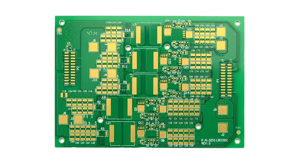
FR4 PCB
FR4: The Standard Baseline Material
FR4 remains the most widely used PCB substrate for cost-sensitive applications operating below 3 GHz. Standard FR4 provides sufficient performance for consumer electronics, industrial controls, and legacy communication systems, where manufacturing cost and process simplicity often take priority over high-frequency performance.
However, FR4 has notable limitations in high-speed applications. Its dissipation factor (Df) typically ranges from 0.018 to 0.025 at 1 GHz and increases at higher frequencies, resulting in higher insertion loss. This makes conventional FR4 unsuitable for demanding applications such as high-speed backplanes, RF circuits, or millimeter-wave designs.
Modern FR4 variants employ optimized resin systems and glass weave architectures to improve electrical characteristics while retaining cost efficiency. These enhanced materials can support frequencies up to around 5 GHz, but their signal integrity and loss performance remain lower than specialized high speed PCB materials like Rogers or Megtron.
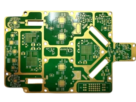
Rogers RO4350B PCB
Rogers High Frequency Materials
Rogers Corporation is a leading provider of high frequency PCB materials tailored for high-speed applications. The Rogers 4000 series supports frequencies up to 40 GHz, with dielectric constants (Dk) ranging from 3.38 to 6.15 and dissipation factors (Df) as low as 0.0027 at 10 GHz, offering excellent signal integrity for high-speed designs.
RO4350B provides a balanced combination of electrical performance and manufacturability. With a controlled Dk of 3.48 and a low Df of 0.0037, it enables precise controlled impedance in high-speed PCB layout while remaining compatible with standard FR4 processing temperatures. This thermal compatibility reduces manufacturing complexity and cost compared to PTFE-based substrates.
Rogers 4835 delivers even lower loss, with a Df of 0.0030, making it ideal for demanding applications such as automotive radar systems at 77 GHz. Its stable electrical properties across temperature variations ensure consistent performance in environments with severe thermal cycling.
Advanced Rogers Materials for Extreme Performance
The Rogers RT/duroid 5880 represents the premium tier of PTFE-based substrates, offering exceptional electrical performance with a Dk of 2.20 and Df of 0.0009 at 10 GHz. These characteristics make it ideal for millimeter-wave applications where insertion loss must be minimized. However, the material requires specialized processing techniques and higher assembly temperatures, increasing manufacturing complexity and cost.
Megtron PCB
Megtron: Optimized for High-Speed Digital Applications
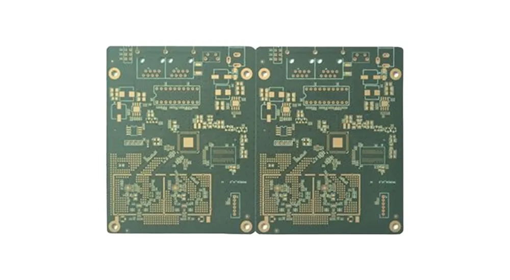
Panasonic’s Megtron PCB series sets a new standard for high speed PCB materials, engineered specifically for digital applications requiring exceptional signal integrity. Unlike traditional high-frequency substrates designed for analog RF performance, Megtron focuses on the unique demands of high-speed digital transmission.
Megtron 6 Performance Characteristics
Megtron 6 delivers excellent performance for data rates up to 25 Gbps, with a dielectric constant (Dk) of 3.17 and a low dissipation factor (Df) of 0.002 at 5 GHz. Its smooth copper-dielectric interface minimizes surface roughness effects, reducing insertion loss and maintaining signal quality over long channel lengths, critical in high-speed PCB design applications.
The material exhibits outstanding Dk stability across frequencies, with variations under ±0.05 from DC to 20 GHz, enabling predictable impedance control and reducing the need for extensive post-layout tuning, which accelerates design cycles for high-speed digital products.
Megtron 7 and Next-Generation Innovations
Megtron 7 further improves performance, offering a Df of 0.0015 at 5 GHz and supporting applications up to 56 Gbps. Advanced polymer chemistry minimizes molecular-level losses while maintaining compatibility with standard multilayer PCB fabrication processes.
Its enhanced thermal performance, with a Tg of 200°C, meets the demanding requirements of high-power digital applications, such as graphics processors and AI accelerators, where power densities can exceed 50 W/cm².
Comprehensive Material Comparison Analysis
| Material Category | Dielectric Constant (Dk) | Dissipation Factor (Df) | Glass Transition Temp (Tg) | Relative Cost | Primary Applications |
|---|---|---|---|---|---|
| Standard FR4 | 4.2 - 4.5 | 0.018 - 0.025 | 130 - 140°C | 1.0x | Consumer, Industrial |
| Enhanced FR4 | 4.0 - 4.2 | 0.012 - 0.018 | 150 - 170°C | 1.2x | Mid-speed Digital |
| Rogers 4350B | 3.48 | 0.0037 | 280°C | 3.5x | 5G, Automotive Radar |
| Rogers 4835 | 3.24 | 0.0030 | 350°C | 4.2x | Millimeter Wave |
| Megtron 6 | 3.17 | 0.002 | 180°C | 2.8x | High-Speed Digital |
| Megtron 7 | 3.12 | 0.0015 | 200°C | 3.2x | 56Gbps+ Applications |
Strategic High Speed PCB Material Selection Guidelines
Frequency-Based Selection Criteria
For applications below 3 GHz, enhanced FR4 provides adequate performance while keeping costs low. The price gap between FR4 and Rogers PCB can exceed 300%, making premium materials justifiable only when electrical performance demands require it.
For designs in the 3–10 GHz range, Rogers 4000 series materials are preferred to maintain low insertion loss and signal integrity. Comparisons of FR4 vs Rogers PCB for high-frequency applications clearly favor Rogers when preserving signal quality is critical.
Digital Speed Considerations
Choosing PCB material for 10Gbps+ designs depends on channel length and loss budget. Short channels under 10 inches may operate successfully on enhanced FR4, whereas longer channels typically require Megtron or Rogers materials to maintain sufficient signal margins.
At 25 Gbps and higher, Megtron PCB vs Rogers PCB performance highlights Megtron’s superior signal integrity. Its smooth copper-dielectric interface and stable Dk minimize high-frequency losses, preserving digital eye patterns in long channels.
Application-Specific Recommendations
PCB substrate selection for 5G depends on implementation. Millimeter-wave front-end modules benefit from Rogers RT/duroid materials for their exceptional high-frequency performance, while baseband processing sections may use Megtron materials for digital optimization and lower cost.
In data center designs, Rogers vs Megtron PCB considerations favor Megtron due to its digital-specific optimizations and thermal stability. Data center applications prioritize signal integrity over broad RF bandwidth, making Megtron materials more suitable than Rogers’ RF-focused heritage.
Advanced Design Considerations
Stackup Architecture Impact
Material selection cannot be divorced from high-speed PCB stackup design considerations. Mixed-dielectric stackups combining different materials for power, ground, and signal layers require careful impedance planning to avoid discontinuities. The interaction between material properties and via design in high-speed PCB applications becomes particularly critical when transitioning between different substrate types.
Signal Integrity Optimization
High speed PCB material comparison for engineers must consider the complete signal integrity picture, including crosstalk and EMI in high-speed PCB applications. Lower-Dk materials generally provide better isolation between adjacent traces, while materials with better Df characteristics reduce far-end crosstalk through improved insertion loss performance.
The difference between high-speed PCB vs standard PCB approaches extends beyond material selection to encompass design methodologies, simulation requirements, and manufacturing controls that ensure electrical performance targets are achieved.
Manufacturing and Supply Chain Considerations
Material availability and supply chain stability represent critical factors often overlooked in initial material selection. Rogers materials benefit from established global supply chains and consistent availability, while Megtron materials may have longer lead times due to their specialized nature.
Processing compatibility with existing manufacturing capabilities affects total cost of ownership beyond material prices. Rogers 4350B processes similarly to FR4, minimizing manufacturing investment requirements. Conversely, PTFE-based materials may require specialized drilling and processing capabilities that increase manufacturing costs.
Future Outlook and Emerging Technologies
The semiconductor industry’s transition to advanced packaging technologies and chiplet architectures is driving demand for even higher-performance substrates. Emerging applications such as 800G optical transceivers and artificial intelligence inference engines require materials with Df values below 0.001 and exceptional thermal performance.
Advanced material developments focus on reducing surface roughness effects, improving thermal conductivity, and enhancing mechanical reliability. These innovations will enable the next generation of high-speed electronic systems operating at data rates approaching 100 Gbps per lane.
Conclusion
Choosing the right high speed PCB material requires balancing electrical performance, thermal stability, manufacturability, and cost. FR4 remains suitable for cost-sensitive designs below 3 GHz, Rogers excels in high-frequency analog applications, and Megtron is optimized for high-speed digital systems.
Effective material selection considers not only performance but also economic and manufacturing feasibility. Collaboration with experienced PCB manufacturers ensures designs leverage advanced substrates without compromising reliability or cost.
At Haoyue Electronics, we support engineers in selecting FR4, Rogers, or Megtron materials to achieve both performance and manufacturability goals. From design consultation to final assembly, we provide integrated solutions for demanding high-speed applications in telecommunications, automotive, and computing.

