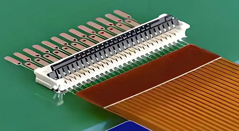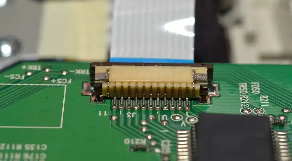
Electronic devices keep getting smaller and more powerful. To make that possible, flexible PCB connectors step in as a key solution. They create a dependable link between soft circuits and rigid boards, allowing more compact designs without sacrificing functionality. From everyday gadgets to aerospace systems, these connectors help keep everything running smoothly.
But it’s not just about making a connection. These components also need to handle physical stress, protect signal quality, and fit into fast-paced production lines. Knowing the specs, design rules, and typical challenges behind these connectors is essential for turning great ideas into reliable products.
Understanding Flexible PCB Connector Technology and Design Principles
Technical Specifications and Performance Parameters
Flexible PCB connectors operate within precisely defined electrical and mechanical parameters that determine their suitability for specific applications. The fundamental performance characteristics include contact resistance, current carrying capacity, and voltage rating, which collectively define the connector’s electrical capabilities.
Contact resistance typically ranges from 20 to 100 milliohms per contact, depending on the contact material and plating specifications. Gold plating thickness varies from 0.05 to 2.54 micrometers, with thicker plating providing enhanced corrosion resistance and lower contact resistance over extended operational periods. Current carrying capacity generally ranges from 0.5 to 3.0 amperes per contact for standard configurations, though specialized high-current variants can accommodate significantly higher loads.
Operating temperature ranges typically span from -40°C to +85°C for standard applications, with extended temperature variants supporting -55°C to +125°C for aerospace and automotive applications. Mechanical specifications include insertion and extraction forces, mating cycles, and flexibility parameters. Insertion forces typically range from 2 to 15 Newtons depending on the connector type and contact count, while high-quality connectors support 500 to 10,000 mating cycles.
| Parameter | Standard Range | High-Performance Range |
|---|---|---|
| Contact Resistance | 50-100 mΩ | 20-50 mΩ |
| Current Rating | 0.5-1.5A | 1.5-3.0A |
| Operating Temperature | -40°C to +85°C | -55°C to +125°C |
| Mating Cycles | 500-1,000 | 5,000-10,000 |
| Insertion Force | 5-15N | 2-8N |
Contact Technology and Termination Methods
The contact technology employed in flexible PCB connectors significantly influences their electrical performance and mechanical reliability. Spring-loaded contacts utilize phosphor bronze or beryllium copper alloys to maintain consistent contact pressure across temperature variations and mechanical stress cycles. These contacts feature gold plating over nickel barrier layers to prevent base metal migration and ensure long-term reliability.
Termination methods for flexible circuits include direct insertion, where the flexible circuit is inserted directly into the connector housing, and crimped terminations, where individual conductors are mechanically attached to connector contacts. Zero insertion force mechanisms employ actuator systems that clamp the flexible circuit after insertion, eliminating mechanical stress during mating operations.
Surface mount termination provides secure mechanical attachment to rigid PCBs through reflow soldering processes. SMT tail configurations include straight, right-angle, and vertical orientations to accommodate various board layout requirements. Through-hole terminations offer enhanced mechanical strength for applications subjected to significant mechanical stress or vibration.
Comprehensive Guide to Flexible PCB Connector Types and Selection
Connector Classification by Mating Mechanism
Zero Insertion Force connectors represent the most sophisticated category of flexible PCB connectors, featuring actuator mechanisms that secure the flexible circuit without applying insertion stress. These connectors utilize sliding or rotating actuators to clamp the flexible circuit after insertion, providing reliable retention while minimizing the risk of conductor damage during assembly operations.
Low Insertion Force connectors employ spring-loaded contacts that compress during insertion, requiring moderate force while maintaining secure retention. These connectors offer an optimal balance between ease of assembly and mechanical retention, making them suitable for applications requiring frequent mating and demating operations.
Friction-lock connectors rely on mechanical interference between the flexible circuit and connector housing to maintain retention. While these connectors offer cost advantages and simple assembly processes, they require careful consideration of flexible circuit thickness tolerances and environmental factors that may affect retention force over time.
| Connector Type | Assembly Ease | Signal Integrity | Flex Durability | Recommended Applications |
|---|---|---|---|---|
| ZIF | ★★★★☆ | ★★★★★ | ★★★★☆ | Mobile devices, display modules, cameras |
| LIF | ★★★☆☆ | ★★★★☆ | ★★★☆☆ | Low-cost consumer electronics, tablets |
| Friction-lock | ★★☆☆☆ | ★★★☆☆ | ★★☆☆☆ | Disposable electronics, simple devices |
| Spring-loaded | ★★★★☆ | ★★★★☆ | ★★★★★ | Automotive, aerospace, industrial equipment |
Pitch and Contact Configuration Options
Contact pitch represents a critical parameter determining the connector’s density and signal routing capabilities. Standard pitch configurations range from 0.3mm for ultra-high-density applications to 2.54mm for power and low-frequency signal applications. Fine-pitch connectors below 0.5mm require precise manufacturing tolerances and specialized assembly techniques.
The relationship between contact pitch and conductor width affects the flexible circuit design and manufacturing feasibility. Trace width and spacing on the flexible circuit must accommodate the connector’s contact geometry while maintaining electrical performance requirements. Manufacturing tolerances become increasingly critical as pitch dimensions decrease, requiring enhanced process control and inspection procedures.
| Pitch Size | Typical Applications | Contact Count Range | Trace Width/Spacing |
|---|---|---|---|
| 0.3–0.4mm | High-density displays, cameras | 20–100 | 0.05/0.05mm |
| 0.5mm | Mobile devices, tablets | 10–80 | 0.075/0.075mm |
| 1.0mm | General electronics | 5–50 | 0.15/0.15mm |
| 1.25mm | Automotive, industrial | 5–40 | 0.2/0.2mm |
| 2.54mm | Power applications | 2–20 | 0.5/0.5mm |
Engineering Considerations for Flexible PCB Connector Implementation
Design Guidelines and Best Practices
Bend Radius and Mechanical Stress Control
Proper flexible PCB connector implementation requires careful consideration of mechanical stress distribution, signal integrity preservation, and manufacturing tolerance accommodation. The flexible circuit design must incorporate appropriate bend radius specifications to prevent conductor fracture and maintain electrical continuity over the expected operational lifetime.
Strain Relief and Structural Reinforcement
Strain relief design becomes critical in applications involving repeated flexing or dynamic mechanical loading. Reinforcement materials such as polyimide stiffeners or FR4 backing plates provide mechanical support at the connector interface while maintaining overall assembly flexibility. The transition zone between rigid and flexible sections requires gradual stiffness changes to distribute mechanical stress effectively.
Signal Integrity and EMI Suppression
Signal integrity considerations include impedance control, crosstalk minimization, and electromagnetic interference suppression. Differential pair routing requires precise trace geometry and spacing control to maintain characteristic impedance within specified tolerances. Ground plane design and via placement strategies significantly influence signal quality in high-frequency applications.
Shielding and Grounding Techniques
EMI shielding may require specialized connector designs incorporating conductive gaskets or metal shields. Grounding strategies must ensure low-impedance return paths while accommodating the mechanical flexibility requirements of the assembly.
Environmental and Reliability Requirements
Thermal Cycling and Expansion Matching
Environmental factors significantly influence flexible PCB connector selection and design implementation. Temperature cycling subjects the connector to thermal expansion and contraction cycles that can affect contact resistance and mechanical retention. Coefficient of thermal expansion matching between the connector housing, contacts, and flexible circuit substrate minimizes thermally induced stress.
Moisture Resistance and Sealing Methods
Humidity exposure can cause corrosion of contact surfaces and degradation of insulation materials. Moisture absorption by polymer housings may affect dimensional stability and electrical properties. Sealed connector designs with gaskets or potting compounds provide protection against moisture ingress in harsh environments.
Vibration and Shock Management
Vibration and shock resistance requires careful attention to contact spring design and housing material selection. Contact normal force must remain within specified limits across the expected vibration spectrum to maintain electrical continuity. Mechanical damping characteristics of the housing material influence the connector’s ability to withstand shock loading without damage.
Chemical and Application-Specific Material Selection
Chemical resistance requirements vary significantly across application environments. Automotive applications may require resistance to fuels, oils, and cleaning solvents, while medical applications demand biocompatibility and resistance to sterilization processes. Material selection must consider both immediate compatibility and long-term stability under exposure conditions.

Industry Applications and Performance Optimization
Application-Specific Requirements
Consumer Electronics
Consumer electronics applications prioritize miniaturization, cost optimization, and manufacturing efficiency. Smartphone and tablet designs require ultra-fine-pitch connectors capable of supporting high-speed digital signals while occupying minimal board space. Display interfaces demand high pin counts with precise impedance control for video signal transmission. Camera modules require specialized connectors supporting both high-frequency digital signals and sensitive analog circuits.
Automotive Systems
Automotive applications emphasize environmental robustness, long-term reliability, and safety compliance. Operating temperature ranges extend beyond consumer electronics requirements, while vibration and shock specifications reflect the harsh automotive environment. Automotive connectors must comply with industry standards such as AEC-Q100 for electronic components and ISO 26262 for functional safety.
Medical Devices
Medical device applications require biocompatible materials, sterilization compatibility, and regulatory compliance with standards such as ISO 13485 and FDA requirements. Patient safety considerations mandate rigorous reliability testing and failure mode analysis. Implantable devices impose additional constraints on material selection and outgassing characteristics.
Aerospace and Defense
Aerospace and defense applications demand the highest levels of reliability, environmental resistance, and performance consistency. Military specifications such as MIL-DTL-83513 define stringent requirements for connector performance under extreme conditions. Space applications require additional considerations for vacuum operation, radiation resistance, and outgassing compliance.
Common Design Challenges and Solutions
Typical Failure Modes and Prevention Strategies
Cold Solder Joints
Cold solder joints represent a frequent assembly defect where insufficient heat or inadequate surface preparation results in poor electrical and mechanical connections. Prevention requires precise reflow temperature profiles, proper flux application, and thorough surface cleaning protocols.
Contact Fatigue
Contact fatigue develops through repeated mating cycles, causing gradual degradation of contact spring force and increased resistance. Material selection plays a critical role, with phosphor bronze and beryllium copper alloys providing superior fatigue resistance compared to standard brass contacts. Proper actuation force limits and contact geometry optimization minimize stress concentrations that accelerate fatigue failure.
Fretting Corrosion
Fretting corrosion occurs when micro-movements between contact surfaces create wear debris that increases resistance over time. This phenomenon becomes particularly problematic in vibration-prone environments where thermal cycling causes differential expansion. Prevention strategies include contact material selection with enhanced corrosion resistance, proper contact normal force design, and environmental sealing to exclude contaminants.
Connector Loosening
Connector loosening results from inadequate retention mechanisms or thermal cycling effects that reduce holding force over time. Design solutions include positive locking mechanisms, retention force verification testing, and material selection that maintains dimensional stability across the operational temperature range.
Signal Integrity Degradation
Signal integrity degradation represents a primary challenge in high-frequency flexible PCB connector applications. Solutions include controlled impedance design, differential pair routing optimization, and minimization of discontinuities at the connector interface. Advanced simulation tools enable pre-design validation of signal integrity performance across the complete interconnect system.
Manufacturing Yield Issues
Manufacturing yield optimization requires careful tolerance analysis and design for manufacturability principles. Connector selection must consider the capabilities and limitations of the flexible circuit manufacturing process. Assembly processes require optimization to minimize handling stress and ensure consistent quality outcomes.
Thermal Management Problems
Thermal management challenges arise in high-power applications where connector resistance contributes to system heat generation. Solutions include contact material optimization, current derating analysis, and thermal interface design. Heat dissipation paths must be carefully considered in the overall system thermal design.
Cost Optimization Constraints
Cost optimization requires balancing performance requirements against manufacturing costs and assembly complexity. Value engineering approaches evaluate alternative connector technologies and designs to achieve target cost objectives while maintaining necessary performance characteristics. Volume considerations significantly influence the optimal connector selection and customization level.
Partner with Haoyue Electronics for Your Flexible PCB Connector Solutions
The complexities of modern flexible PCB connector implementation require both technical expertise and manufacturing excellence to achieve optimal results. Design engineers and hardware developers benefit from partnering with experienced manufacturers who understand the intricate relationships between connector selection, circuit design, and assembly processes.
At Haoyue Electronics, our engineering team collaborates closely with customers to optimize connector selection, flexible circuit design, and assembly processes for maximum reliability and cost-effectiveness. Our comprehensive approach addresses the complete development cycle from initial concept validation through volume production optimization.
Our state-of-the-art PCB manufacturing and assembly facilities support the complete range of flexible PCB connector technologies, from ultra-fine-pitch consumer electronics applications to ruggedized aerospace and automotive systems. We provide comprehensive design support, prototyping services, and volume production capabilities to bring your innovative electronic designs to market efficiently.
Contact Haoyue Electronics today to discuss your flexible PCB connector requirements and discover how our engineering expertise can enhance your next electronic product development project.

