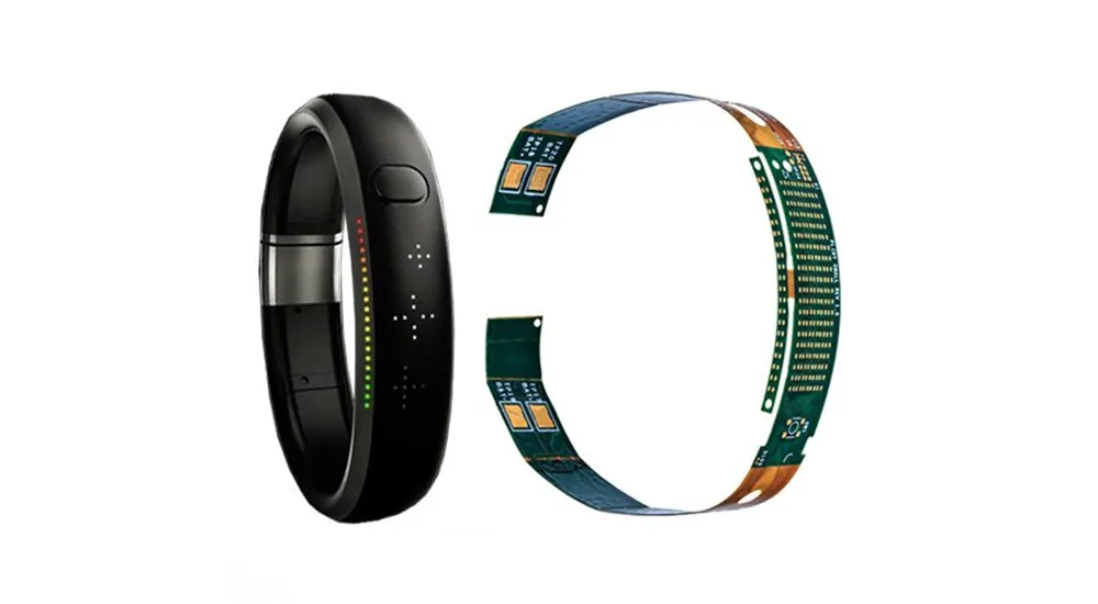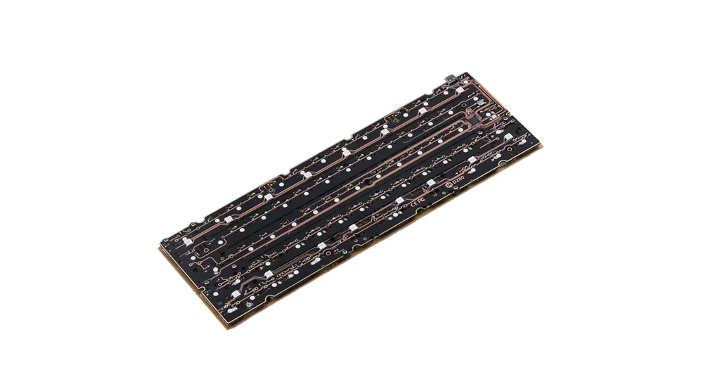
The fundamental distinction between these technologies lies in their substrate materials and manufacturing precision capabilities. Flex cut PCB manufacturing enables three-dimensional circuit configurations that bend and conform to complex geometries, while non-flex cut PCB production focuses on creating robust, dimensionally stable circuits for fixed mounting applications.
Understanding PCB Cutting Technologies and Manufacturing Processes
Flex Cut PCB Manufacturing Fundamentals
Flex cut PCB manufacturing employs laser cutting systems with tolerances as tight as ±0.025mm, utilizing CO2 or UV lasers operating at wavelengths optimized for polyimide substrates. These precision cutting systems achieve speeds of 100–500mm/minute while maintaining edge quality that prevents delamination and copper trace damage. The process eliminates mechanical stress typically associated with traditional cutting methods, preserving the integrity of flexible circuit materials.
The manufacturing process begins with flexible substrate preparation, typically using polyimide materials with excellent thermal stability ranging from –269°C to +400°C. Advanced flex cut systems incorporate vision alignment systems and automated handling equipment to maintain consistent cutting quality across production volumes. Post-cutting inspection utilizes high-resolution optical systems to verify edge quality and dimensional accuracy.
Non-Flex Cut PCB Production Methods
Non-flex cut PCB manufacturing utilizes mechanical routing with carbide end mills or diamond-coated saw blades optimized for rigid substrates. These conventional PCB fabrication methods achieve tolerances of ±0.1mm and accommodate substrate thicknesses from 0.4mm to 6.0mm. The cutting speeds range from 25–75mm/minute, depending on substrate composition and required edge finish quality.
Standard rigid PCB materials include FR4 epoxy glass composite offering mechanical strength of 415 MPa tensile strength and glass transition temperatures of 170–180°C. Specialized applications may utilize ceramic substrates, metal core PCBs, or high-frequency materials like Rogers RT/duroid for specific performance requirements. The established manufacturing infrastructure enables cost-effective production with shorter lead times compared to flex cut alternatives.
Substrate Material Characteristics and Selection
Flexible PCB substrates predominantly use polyimide films with low dielectric constants (3.4–3.5) and superior chemical resistance. Alternative flexible materials include polyethylene terephthalate (PET) for cost-sensitive applications and polyetheretherketone (PEEK) for extreme temperature environments. Adhesive systems play critical roles in multilayer flex constructions, with acrylic and epoxy-based adhesives providing different thermal and mechanical properties.
Rigid PCB substrates focus on thermal management and electrical performance optimization. FR4 remains the industry standard for general applications, while specialized materials address high-frequency, high-temperature, and high-power requirements. Material selection directly impacts manufacturing costs, with exotic substrates requiring specialized processing equipment and longer lead times.
For engineers evaluating fundamental design approaches and material selection strategies across different PCB technologies, refer to our Rigid vs Flex PCB Selection Guide for comprehensive design-level comparison and application guidance.
Technical Specifications and Performance Analysis
Precision Manufacturing Comparison
| Parameter | Flex Cut PCB | Non-Flex Cut PCB |
|---|---|---|
| Cutting Tolerance | ±0.025mm | ±0.1mm |
| Edge Quality | Smooth, sealed edges | May require secondary finishing |
| Minimum Feature Size | 0.05mm | 0.1mm |
| Processing Speed | 100-500mm/min | 25-75mm/min |
| Heat Affected Zone | <0.01mm | Minimal (mechanical) |
| Material Utilization | 90-95% | 75-85% |
Mechanical Reliability and Durability
Flex cut PCBs demonstrate exceptional fatigue resistance, withstanding over 100,000 flex cycles at recommended bend radii without trace fracture. The precision laser cutting process creates sealed edges that prevent moisture ingress and contamination, contributing to enhanced long-term reliability. Bend radius calculations typically maintain minimum ratios of 6–10 times total thickness for dynamic flexing applications.
Non-flex cut PCBs provide excellent dimensional stability essential for applications requiring precise component positioning and mechanical mounting. The rigid substrate construction offers superior vibration resistance in fixed installations, with minimal thermal expansion affecting component placement accuracy. Mechanical reliability includes resistance to shock and vibration in demanding industrial environments.
Electrical Performance Characteristics
Flexible PCB designs enable three-dimensional signal routing that minimizes electromagnetic interference and reduces crosstalk in compact assemblies. Controlled impedance implementation requires careful consideration of bend radius effects, typically resulting in ±10% impedance variation during flexing cycles. The flexible substrate materials exhibit lower parasitic capacitance in bent configurations compared to rigid alternatives.
Rigid PCB construction provides consistent electrical characteristics essential for high-frequency and high-speed digital applications. Predictable dielectric properties and stable geometry enable precise impedance control and minimize signal degradation in critical timing applications. Superior thermal dissipation capabilities support high-current applications requiring effective heat management.

Applications and Industry Use Cases
Automotive and Transportation Systems
Modern automotive electronics increasingly utilize flexible PCB technology for dashboard displays, seat control modules, and infotainment systems where space constraints and vibration resistance are critical. Automotive qualification requirements include AEC-Q200 testing standards and operating temperature ranges from -40°C to +85°C. The three-dimensional routing capabilities enable innovative designs that conform to vehicle interior contours.
Traditional rigid PCB technology remains essential for automotive power management systems, engine control units, and safety-critical applications requiring robust mechanical mounting and thermal dissipation. These applications benefit from the dimensional stability and cost-effectiveness of conventional PCB construction methods.
Medical Device Innovation
Flexible PCB technology enables breakthrough innovations in medical device miniaturization, particularly in implantable devices, wearable health monitors, and minimally invasive surgical instruments. Biocompatibility requirements necessitate specialized substrate materials and surface treatments compatible with human physiology. The conformable nature of flexible circuits reduces patient discomfort and improves device integration.
Rigid PCB technology continues serving critical roles in medical imaging equipment, patient monitoring systems, and diagnostic instruments where electrical performance and electromagnetic shielding requirements supersede space constraints. The established manufacturing base and regulatory approval processes favor rigid PCB solutions for life-critical applications.
Consumer Electronics and Mobile Technology
The proliferation of foldable smartphones, wearable technology, and ultra-thin laptops drives increasing adoption of flexible PCB technology. These applications require sophisticated thermal management solutions and multilayer stackup designs optimized for repeated flexing cycles. Consumer electronics manufacturers leverage flexible PCB technology to achieve competitive advantages in product differentiation and miniaturization.
Rigid PCB technology remains fundamental in desktop computers, home appliances, and power electronics where cost optimization and manufacturing efficiency take precedence over form factor constraints. The mature supply chain and established design practices support high-volume production requirements.
Aerospace and Defense Electronics
Both flexible and rigid PCB technologies serve essential functions in aerospace and defense electronics, with selection criteria based on specific mission requirements, environmental conditions, and reliability standards. Flexible PCB solutions excel in satellite deployable systems and missile guidance applications requiring mechanical compliance and space optimization.
Rigid PCB technology provides the foundation for radar systems, communication equipment, and avionics applications where electrical performance, thermal management, and manufacturing repeatability are paramount. The established qualification processes and supply chain maturity support critical defense applications.

Conclusion and Technology Selection Guidelines
The choice between flex cut vs non flex cut PCB technology requires comprehensive evaluation of application requirements, environmental conditions, cost constraints, and manufacturing volumes. Flexible PCB solutions provide superior performance for applications demanding mechanical flexibility, space optimization, and three-dimensional circuit configurations. Rigid PCB technology remains optimal for applications requiring thermal management, cost efficiency, and established manufacturing processes.
Emerging trends indicate increasing convergence between these technologies, with rigid-flex PCB designs incorporating both cutting methodologies within single assemblies. Advanced materials development and manufacturing process innovations continue expanding the application envelope for both technology approaches.
We combine advanced manufacturing capabilities with experienced engineering support to help you navigate complex design challenges and achieve your project objectives. Whether you need prototype development or high-volume production, our team provides the technical guidance and manufacturing excellence necessary to bring your electronic innovations to market successfully.
Frequently Asked Questions
What are the main cost differences between flex cut and non-flex cut PCBs?
Flex cut PCBs typically cost 2-5 times more than equivalent rigid PCBs due to specialized materials, precision manufacturing equipment, and lower production volumes. However, the elimination of connectors and cables in three-dimensional assemblies can offset higher PCB costs through reduced system complexity and improved reliability.
Can flex cut PCBs handle high-power applications?
Flexible PCBs can handle moderate power levels, typically up to 2-3 watts per square inch, depending on substrate materials and thermal management design. High-power applications generally favor rigid PCB technology due to superior thermal dissipation capabilities and larger copper pour areas.
What design considerations are critical for flex cut PCB reliability?
Critical design considerations include proper bend radius calculations (minimum 6-10 times total thickness), copper trace routing perpendicular to bend lines, stiffener placement at connector areas, and via placement away from high-stress zones. Teardrops and curved traces improve mechanical reliability compared to sharp angles.
How do lead times compare between flex cut and non-flex cut PCB manufacturing?
Non-flex cut PCBs typically require 5-10 days for prototypes and 1-3 days for production volumes due to established manufacturing infrastructure. Flex cut PCBs generally require 10-15 days for prototypes and 3-5 days for production volumes due to specialized processing requirements and quality control procedures.
What environmental testing standards apply to flexible PCBs?
Flexible PCBs undergo similar environmental testing to rigid PCBs, including thermal cycling, humidity exposure, and mechanical stress testing. Additional flex-specific tests include dynamic flexing cycles, crease resistance, and tear strength evaluation. Military and aerospace applications require compliance with MIL-STD-810 and similar standards.

